
TM 55-2815-574-24
0111
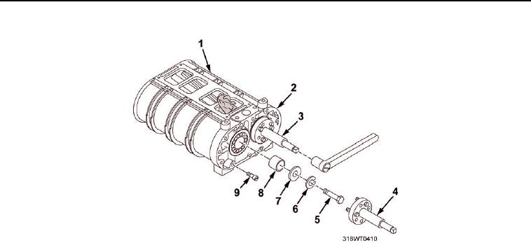
DISASSEMBLE - Continued
Figure 5.
a.
Remove fuel pump drive bolt (Figure 5, Item 5), lock washers (Figure 5, Item 6), flat washer
(Figure 5, Item 7) and spacer (Figure 5, Item 8).
b.
Remove two fillister head screws (Figure 5, Item 9) securing front end plate (Figure 5, Item 2) to
blower housing (Figure 5, Item 1).
NOTE
The inner races of the bearing assemblies will remain on the shaft of the rotor. The lip
type oil seals will be damaged and need to be replaced with lip type oil seals or double
lip type, teflon oil seals.
c.
Back out the center screws of both pullers (Figure 5, Item 4 and Figure 5, Item 3).
d.
Position both pullers (Figure 5, Item 4 and Figure 5, Item 3) on front end plate (Figure 5, Item 2).
CAUTION
Ensure the six 1/4 in. x 20 x 1 1/4 in. bolts are threaded all the way into the end plate
to provide minimum anchorage for the pullers to eliminate possible damage to the
blower and plate.
e.
Secure the pullers (Figure 5, Item 4 and Figure 5, Item 3) to front end plate (Figure 5, Item 2) with six
1/4 in. X 20 X 1 1/4 in. bolts.
f.
Rotate two pullers simultaneously clockwise and remove end plate (Figure 5, Item 2) from the blower
housing (Figure 5, Item 1).
g.
Remove pullers (Figure 5, Item 4 and Figure 5, Item 3) from front end plate (Figure 5, Item 2).
13.
Remove cloth from between rotors. (Figure 6, Item 1 and Figure 6, Item 3)
14.
Remove blower rotors (Figure 6, Item 1 and Figure 6, Item 3) from the blower housing (Figure 6, Item 2).