
TM 55-2815-574-24
0111
DISASSEMBLE - Continued
NOTE
Step 16 is only necessary on older style seals on turbocharged blowers. Upon installation,
the lip type or double lip type teflon oil seal should be used.
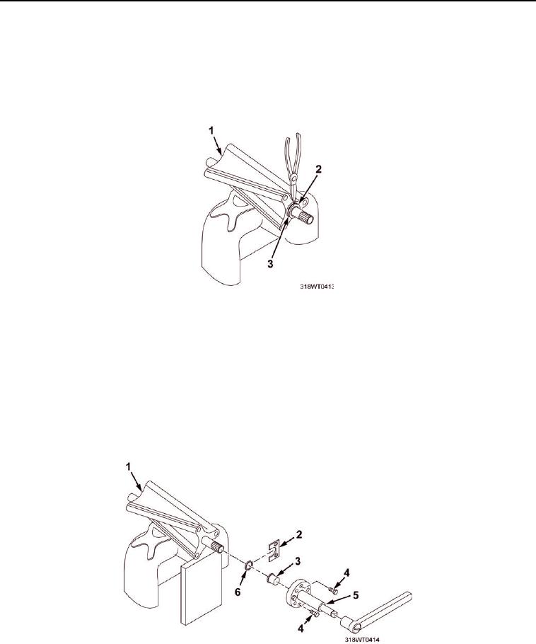
16.
Remove seal rings (Figure 8, Item 2) and seal ring carriers (Figure 8, Item 3) and bearing race (Figure 9,
Item 3) from rotor shafts (Figure 8, Item 1).
Figure 8.
a.
Clamp one lobe of a rotor (Figure 8, Item 1) in a vice equipped with two soft jaw vice caps tightened
only enough to hold the rotor (Figure 8, Item 1) stationary.
b.
Remove oil seal ring (Figure 8, Item 2) from the seal ring carrier (Figure 9, Item 6) with a pair of
expanding snap ring pliers.
c.
Place seal ring carrier remover adaptor (Figure 9, Item 2) over the seal ring carrier
(Figure 9, Item 37) ensuring the adaptor is seated securely into the groove of the seal ring carrier
(Figure 9, Item 37).
Figure 9.