
TM 55-2815-574-24
0111
DISASSEMBLE - Continued
7.
Remove timing gears (Figure 2, Item 3 and Figure 2, Item 8).
NOTE
Both gears must be pulled at the same time.
a.
Back out the center screws of both pullers (Figure 2, Item 4).
b.
Position both pullers (Figure 2, Item 4) on timing gears (Figure 2, Item 3 and Figure 2, Item 8).
c.
Secure pullers (Figure 2, Item 4) to timing gears (Figure 2, Item 3 and Figure 3, Item 8) with 5/16 in.
X 24 X 1 1/2 in. bolts.
1.
Use two bolts on the left hand timing gear (Figure 3, Item 8).
2.
Use three bolts on the right hand timing gear (Figure 3, Item 3).
d.
Turn two puller screws (Figure 2, Item 4) simultaneously clockwise and remove timing gears
(Figure 2, Item 3 and Figure 2, Item 8) from the rotor assembly shafts (Figure 2, Item 2 and Figure 2,
Item 1).
e.
Remove pullers (Figure 2, Item 4) from timing gears (Figure 2, Item 3 and Figure 2, Item 8).
8.
Remove shims (Figure 2, Item 9) and gear spacers (Figure 2, Item 10) from the rotor assembly shafts
(Figure 2, Item 2 and Figure 2, Item 1).
NOTE
Count the number of shims and measure the thickness to ensure an identical replacement
when reassembling the blower.
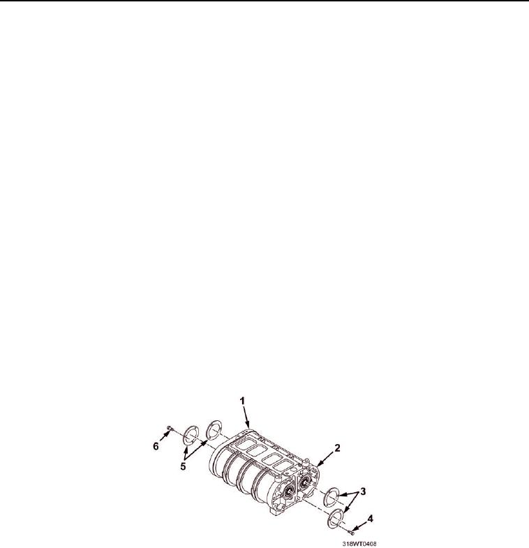
9.
Remove twelve self-locking screws (Figure 3, Item 4 and Figure 3, Item 6) securing four rotor shaft bearing
retainers (Figure 3, Item 5 and Figure 3, Item 3) to the front end plate (Figure 3, Item 2) and rear end plate
(Figure 3, Item 1).
Figure 3.
10.
Remove four shaft bearing retainers (Figure 3, Item 5 and Figure 3, Item 3).
11.
Remove blower rear end plate (Figure 3, Item 1) from the blower housing (Figure 4, Item 3).