
TM 55-2815-574-24
0128
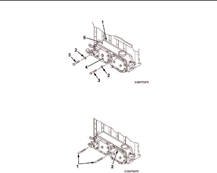
REMOVAL - Continued
Figure 4. Cover Plate Removal.
16.
Install two studs (Figure 5, Item 1) into oil cooler mounting plate (Figure 4, Item 1) through
holes (Figure 5, Item 2).
Figure 5. Oil Cooler Studs Installation.
NOTE
Before removing following bolt, note its location as it is smaller than remaining bolts and
must be set aside for installation in same location.
17.
Remove bolt (Figure 6, Item 4) and washer (Figure 6, Item 5) from cover plate (Figure 6, Item 6).
18.
Remove remaining 12 cover bolts (Figure 6, Item 3) and lockwashers (Figure 6, Item 2) securing cover
plates (Figure 6, Item 6) and oil cooler housing (Figure 6, Item 7) to oil cooler mounting plate
(Figure 6, Item 1).