
TM 55-2815-574-24
0128
REMOVAL
WARNING
Remove all jewelry before conducting maintenance. Do not wear watches, rings,
identification tags, or other jewelry which could short across electrical components or catch
on vehicle components. Failure to comply may result in personnel injury or death.
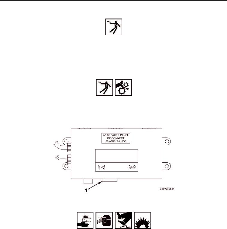
1.
Place A3 breaker switch (Figure 1, Item 1), located on A10 panel, in OFF position. Refer to
TM 55-1925-205-10 for breaker location.
WARNING
Before attempting any maintenance, ensure power supply (switches, circuit breakers, etc.)
has been disconnected and locked/tagged out against unauthorized accidental start-up or
else death or serious injury due to electric shock and/or moving machinery could occur.
2.
Lock Out/Tag Out (LO/TO) A3 breaker switch (Figure 1, Item 1). Refer to FM 4-01.502 for LO/TO procedure.
Figure 1. A3 Breaker Switch.
WARNING
Fuel/solvent/oil is slippery and may cause falls. Wipe up spillage immediately with
rags. Dispose of materials in accordance with local hazardous waste disposal
procedures. Failure to comply may result in personnel injury or death and/or
damage to equipment.
Oils and fluids are flammable and may cause irritation to the eyes or skin. Use in
well-ventilated areas and keep away from heat and open flame. Wear protective
goggles and clothing. In case oil or fluid comes in contact with:
Eyes, flush immediately with water.
Skin, wash with soap and water.
Failure to comply may result in personnel injury or death.
3.
Position drain pan under oil filter supply line (Figure 2, Item 1) and return line (Figure 2, Item 8).