follower fails to revolve and the cams wipe the same
INSPECTING AND REPAIRING
surface each time the camshaft revolves.
CAMSHAFTS
Normal use will cause surface disintegration,
usually as the hardened surfaces begin to fatigue. The
condition is aggravated by abrasive particles. Nicks and
dents on rollers will also cause disintegration.
You must make constant checks for defective rollers
or surfaces and for nicks, scratches, or dents in the
camshaft. Whenever you find a defective cam follower,
you should replace it. In roller-type cam followers you
must replace a worn cam follower body and guide or
roller needle bearings (if used).
Defective or poorly operating valve adjusters allow
clearance or lash in the valve gear. Noisy operation of a
lash adjuster indicates that there is insufficient oil in the
cylinder of the unit. When you discover a noisy lash
adjuster and the oil supply or pressure is not the source
of trouble, remove and disassemble the unit according
to the manufacturer’s instructions.
Since the parts of lash adjusters are not
interchangeable, disassemble only one unit at a time.
Check for resinous deposits, abrasive particles, a stuck
ball check valve, a scored check valve seat, and
excessive leakage. Carefully wash all parts of the
hydraulic lash adjuster in kerosene or diesel fuel. Check
such parts as the cam follower body, plunger or piston,
and hydraulic cylinder for proper fit.
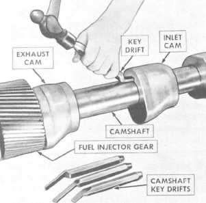
Camshafts can be saved when the cams alone are
damaged, if the cams are of the individual type, since
such cams may be removed and replaced. Figure 3-17
illustrates the method of removing an individual cam
from its shaft.
When you remove a camshaft from an engine, clean
it thoroughly with either kerosene or diesel fuel. After
cleaning the shaft, dry it with compressed air. After
cleaning the cam and journal surfaces, inspect them for
any signs of scoring, pitting, or other damage.
When you remove or insert a camshaft through the
end of the camshaft recess, rotate it slightly. Rotating the
camshaft allows it to enter easily and reduces the
possibility of damage to the cam lobes and bearings.
After you visually inspect a camshaft, place it on
V-blocks and measure the shaft runout by using a dial
indicator. When you measure the runout, take the
out-of-roundness into consideration. Compare your
measurements to the manufacturer’s specifications.
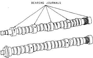
Also, measure the camshaft bearing journals with a
micrometer. Figure 3-18 illustrates a camshaft with
bearing journals.
A camshaft needs to be replaced if the following
conditions occur:
1. The lobes are damaged, as lobes cannot be
repaired.
2 . R u n o u t e x c e e d s t h e m a n u f a c t u r e r ’ s
specifications.
3. Wear on the shaft bearing journals exceeds the
manufacturer’s specifications.
4. The keyways are damaged.
Figure 3-18.—Camshaft with bearing journals in a V-type
engine.
Figure 3-17.—Removing an individual cam.
3-13


