
get the points for the number 4 elements in the
circumference of the upper section of the T, or equal to
stretchout.
twice the distance that you stepped off in the half-plan.
The height of the stretchout, obtained by projection, is
14. Through each of the points located, draw the
equal to the maximum height of the T. The height is
element lines parallel to line 1.
equal to the length of the longest element in the side
15. Project the elements of the side elevation view
elevation--in figure 12-46, element number 4.
to the correspondingly numbered elements in the
9. Step off, locate, and number the element lines
stretchout. Connect the intersecting points with curved
in the stretchout.
lines to outline the hole.
10. Project the points of intersection locating the
16. Add seams to the stretchout as required.
miter in the side elevation. Draw the curve through these
Remember, the amount you will allow for seams will
points.
depend upon the method you plan to use for joining.
11. Now, using the circumference and length of the
When the layout is completed, transferred to sheet
main pipe for dimensions, draw the stretchout for the
metal, and formed, you should have a shape that looks
like the one shown in figure 12-48.
main pipe as shown in figure 12-47.
You have been shown how to develop patterns for
12. Bisect the length of the stretchout with an
a drip pan or box by the straight line angular method of
element line, and number that line 1.
development, and methods for making stretchouts for
13. Set your dividers for the distance from 1 to 2
elbows, pipe intersection angles, and T-joints by the
in the half-plan in the elevation. Using this radius and
parallel line method. Each of these methods has many
the point at which line 1 intersects the right-hand edge
more applications and you will use them often.
of the stretchout, scribe an arc on either side of 1 on the
However, you would not be able to develop some of the
edge of the stretchout. Number each of these points 2.
patterns that you will run into without a working
Now, setting the dividers for the distance from 1 to 3 in
knowledge of the method for radial line pattern
the half-plan of the elevation, scribe arcs, using 1 as a
development.
center, on either side of element 1 in the stretchout.
Number both of these points 3. Repeat the procedure to
RADIAL LINE METHOD
The radial line method of pattern development uses
some of the features of parallel line development. You
will recognize them when you lay out a frustum of a
right cone. You are familiar with the shape of a cone. A
right cone is one that would stand straight, up and down,
when resting on its large end. In other words, a center
line drawn from the point, or vertex, to the base line,
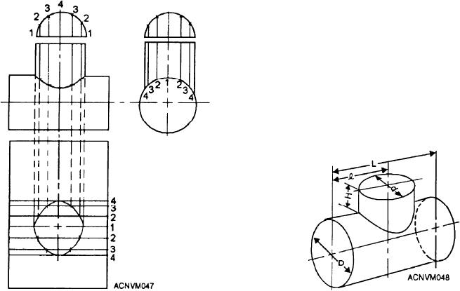
would form right angles with that line. The frustum of
Figure 12-48.--Pictorial view of a T-joint.
Figure 12-47.--Stretchout of the main pipe in the T-joint.
12-18