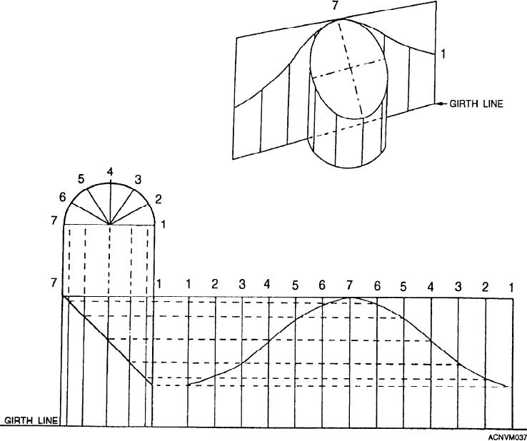
4. Draw measuring lines perpendicular to the
This includes such shapes as the cylinder and prism and
their many variations.
stretchout lines of the pattern.
You will have to use certain fixed principles as
5. Draw lines from the points of intersection of the
follows:
miter line, in the right view, intersecting similarly
1. First, draw a plan and an elevation of the desired
numbered measuring lines drawn from the stretchout,
shape showing the parallel lines of the solid in their
to show the outline of the development.
actual lengths.
2. Visualize the pattern from an angle in which the
6. Trace a line through the points thus obtained to
top, front, and side views are all present, as shown in
give the desired pattern.
figure 12-36.
Now, let us develop a layout of an intersected pipe
3. Draw a stretchout or girth line perpendicular to
following the parallel line method, step by step. A pipe
the parallel lines of the solid. Each space contained in
like this could be used as a ventilation pipe on a slanting
the section or plan view will be placed on the stretchout
lines (fig. 12-37).
roof. Follow the instructions, checking each step with
Figure 12-37.--Stretchout showing a girth line.
12-13

