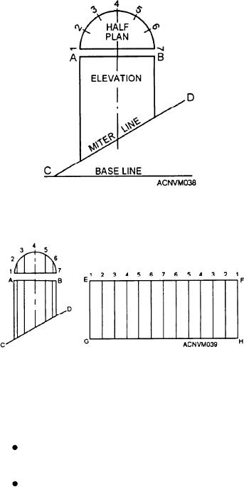
the illustration shown in figure 12-38. Then break out
your layout tools and a sheet of template paper and try
your skills at drawing an intersected pipe layout.
First, construct a base line. After the base line, draw
your miter line at the same degree of angle as that of the
slanting roof or inclined plane, as shown in figure
12-38. The elevation is the front view. Line AB
represents the diameter of the pipe. The distance
between line AB and the miter line is the height of the
pipe, which will vary around the circumference of the
pipe.
Now determine the center of line AB, and construct
a center line as shown in figure 12-38. Set your dividers
for one-half the distance of line AB. Develop the plan
by the following steps:
Figure 12-38.--Elevation and plan of intersected pipe.
1. Construct line 1-7 parallel to and just above AB.
Using the point at which the center line of the elevation
intersects line 1-7, swing an arc with the dividers and
complete the half-plan as shown.
2. Step off the circumference of the half-plan with
the dividers into six equal parts. To do this, place one
leg of your dividers at point 1. With the same
measurement used to scribe the half-plan, scribe a mark
on the arc at point 3. Then from point 3 scribe a mark
at point 5. You now have three equal parts. Bisect these
three sections as an arc and you end up with your
Figure 12-39.--Development of layout for intersected pipe.
required six equal parts.
3. Set your straightedge at right angles to the center
stretchout for the elevation. You may use either of two
line. With the straightedge as a base line, use the flat
methods:
steel square to draw lines parallel to the center line by
the method shown earlier in figure 12-3. The parallel
Measure and transfer the measurement from the
lines must be drawn from the points where the arcs
elevation to the stretchout with your dividers.
intersect the circumference of the half-plan to the miter
Project the points in the elevation to the
line (fig. 12-39).
stretchout by parallel projection lines (broken
4. with the straightedge draw EF (an extension of
lines).
line AB), and step off twice the distance you stepped off
Whichever method you use, the stretchout will be
in the circumference of the half-plan.
the same. However, your measurements must be
5. Draw line GH the same length as EF parallel to
accurate. Try both methods and make a habit of using
EF so that lines drawn from G to E and from H to F will
the one that comes easiest to you.
both be perpendicular. The distance between line EF
To develop your pattern by the use of dividers,
and line GH will be equal to the greatest height of the
follow these step-by step instructions, working from
elevation.
figure 12-39.
6. Through the points located on the extended line,
1. Take your dividers and set them to the distance
by stepping off with the dividers, draw parallel lines at
of line 1 where it intersects line AB to its intersection
right angles to the line extended from AB.
on line CD.
7. Number these lines in the proper order as shown
2. Transfer this measurement to the two lines
(from 1 to 7 and back to 1).
numbered 1 in the stretchout. Use line EF as your base
line for the measurements on the strecthout, and scribe
You are now ready to transfer the miter line CD in
an arc on line 1.
the elevation to the stretchout and thus form the
12-14

