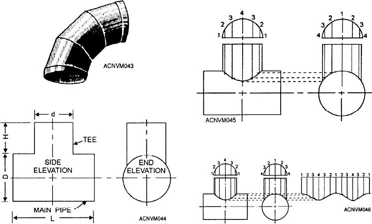
You have seen that you must draw an elevation and
5. Number the elements of the plan as shown. The
plan is numbered from 1 to 4 and back to 1 because each
a plan view. For the intersected pipe and the elbow, it
quarter section of the intersection, or miter, of the two
was necessary to draw only one elevation and plan view.
pieces is the same as any other quarter section in the
However, some developments will require two or more
elevation. If the intersection of the T was other than a
elevations. An example of this type of development is
90-degree angle, you would number from 1 to 7 as you
the T-joint (fig. 12-44).
did in developing the pattern for the elbow. As you can
To develop the T-joint, you must draw a side
see, the number 4 element on the front view is in the
center. If you rotate the T to look at the end view, the
elevation and an end elevation as well as plan views.
number 4 element is also rotated to represent its fixed
For the side elevation, draw the object exactly as you
position as the front and center element.
would see it, looking directly at the side of the T. For
the end elevation, draw the object exactly as you would
6. Extend lines parallel to the center lines in each
of the views from the numbered points. In the end view,
see it if you were looking through the opening.
these lines will be drawn to the main pipe. To determine
Follow these steps to construct the side and end
the lower end of the lines in the side elevation, proceed
elevation as shown in figure 12-44:
as follows: Place the straightedge at right angles to the
number 4 vertical element of the end view. Draw a
1. Draw a horizontal center line.
broken horizontal line from the number 4 element of the
2. Construct two vertical parallel lines
end view to the number 4 vertical element of the side
perpendicular to the center line, leaving sufficient space
view. Connect the other like-numbered elements in the
between them to lay out the side and end elevations.
same manner. Remember that there are two elements
These lines will form the center lines for the elevations.
numbered 3, 2, and 1 in the side elevation to be
connected.
3. Draw the plan view above the constructed
elevations, as shown in figure 12-45.
7. Draw a curve through the intersections you
have just located on the side view.
4. Step off the circumference of the plan view into
8. Now look at figure 12-46. To the right of the
seven equal spaces with your dividers.
elevations, draw a stretchout equal in length to the
Figure 12-43.--Pictorial view of 8 five-piece elbow.
Figure 12-45.--Transferring elements to obtain miter line.
Figure 12-44.--Side and end elevation of a T-joint.
Figure 12-46.--Stretchout of the T.
12-17

