
TM 55-2815-574-24
0052
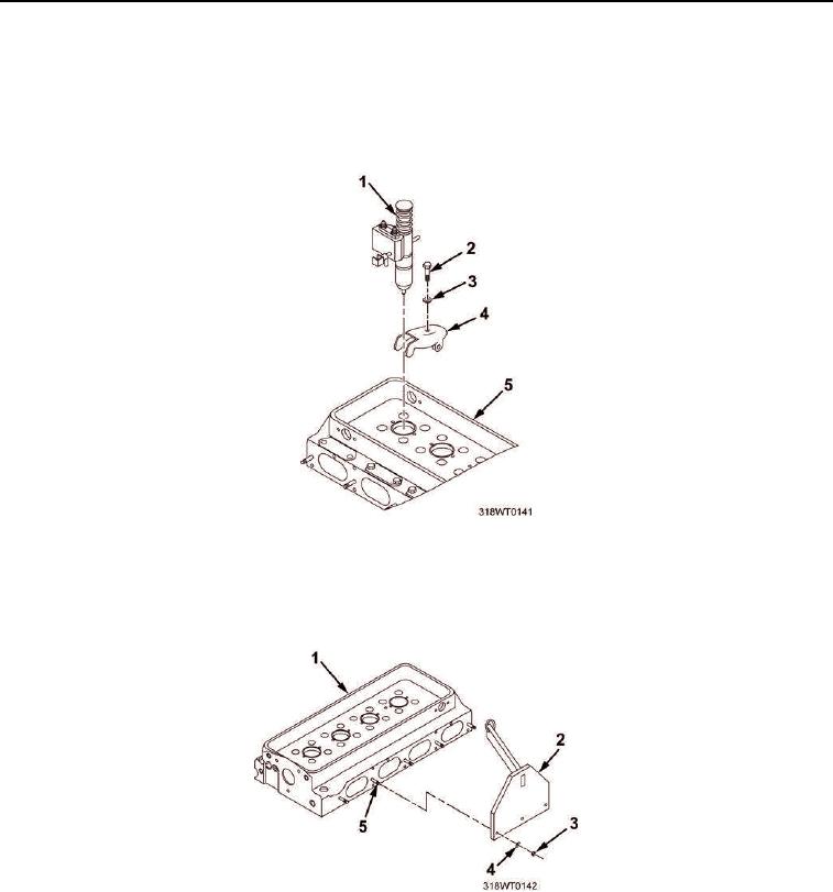
TESTING - Continued
30.
Remove four bolts (Figure 8, Item 2) and convex washers (Figure 8, Item 3) from clamps (Figure 8, Item 4).
31.
Remove clamps (Figure 8, Item 4) from four dummy injectors (Figure 8, Item 1).
32.
Remove dummy injectors (Figure 8, Item 1) from cylinder head (Figure 8, Item 5).
Figure 8. Dummy Injector Removal.
33.
Remove three nuts (Figure 9, Item 3), washers (Figure 9, Item 4), and lifting fixture (Figure 9, Item 2) from
cylinder head (Figure 9, Item 1) exhaust manifold studs (Figure 9, Item 5).
Figure 9. Lifting Fixture Removal.