
TM 55-2815-574-24
0052
TESTING - Continued
5.
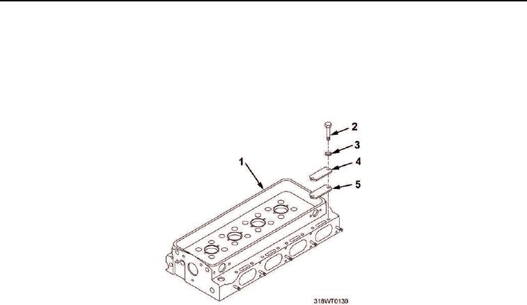
Position four gaskets (Figure 6, Item 5) on cylinder head (Figure 6, Item 1).
6.
Position four cover plates (Figure 6, Item 4) on cylinder head (Figure 6, Item 1).
7.
Install eight bolts (Figure 6, Item 2) and copper washers (Figure 6, Item 3) on cylinder head
(Figure 6, Item 1). Tighten bolts securely.
Figure 6. Cover Plates on Cylinder Head.
8.
Align pressure checking tool test fixture (Figure 7, Item 5) on water inlet ports (Figure 7, Item 6).
9.
Install four bolts (Figure 7, Item 1) with washers (Figure 7, Item 2) in fixture (Figure 7, Item 5).
10.
Install nuts (Figure 7, Item 12) finger tight on bolts (Figure 7, Item 1).
11.
Install six holddown bolts (Figure 7, Item 3) with washers (Figure 7, Item 4).
NOTE
Do not overtighten holddown bolts on test fixture. Overtightening will distort rubber
stoppers and seal outer diameter of water nozzles, preventing the detection of a leak.
12.
Tighten bolts (Figure 7, Item 3), using torque wrench and socket set, evenly until rubber stoppers
(Figure 7, Item 13) start to distort, at approximately 60 in-lb (6.78 Nm).
13.
Tighten nuts (Figure 7, Item 12).
14.
Position pressure checking tool air supply plate (Figure 7, Item 8) onto thermostat end of cylinder head
(Figure 7, Item 7).
15.
Install four bolts (Figure 7, Item 10) and washers (Figure 7, Item 11) into plate (Figure 7, Item 8). Tighten
bolts.
16.
Connect air hose with dial gauge (Figure 7, Item 9) to air supply plate (Figure 7, Item 8).