
TM 55-2815-574-24
0052
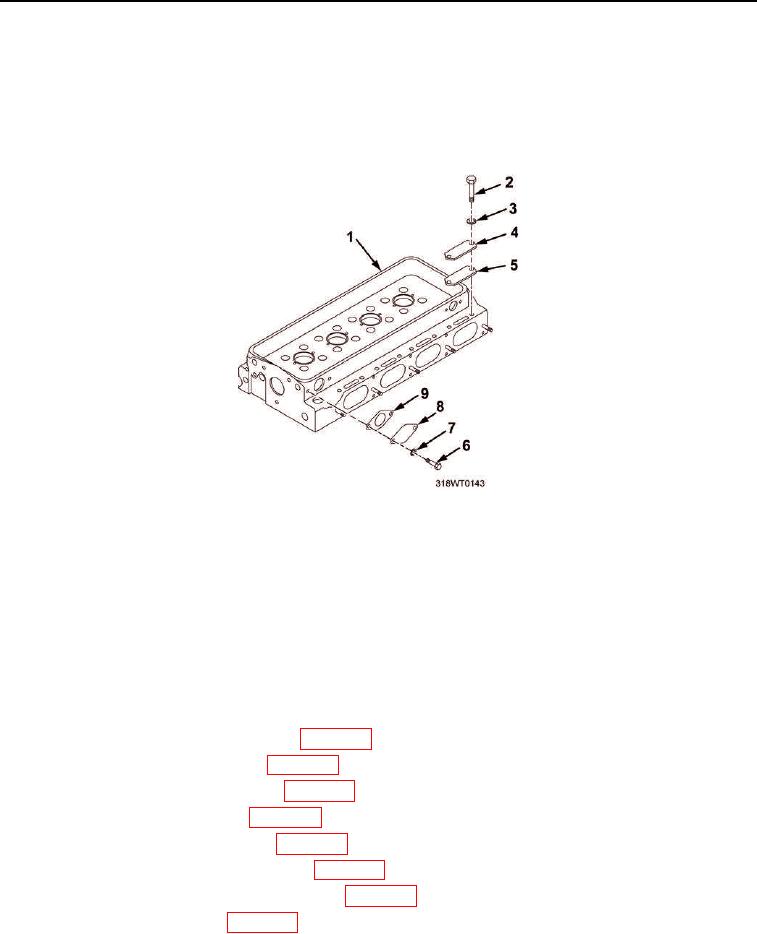
TESTING - Continued
34.
Remove eight bolts (Figure 10, Item 2) and copper washers (Figure 10, Item 3) securing coverplates
(Figure 10, Item 4) to cylinder head (Figure 10, Item 1).
35.
Remove four cover plates (Figure 10, Item 4) from cylinder head (Figure 10, Item 1).
36.
Remove four gaskets (Figure 10, Item 5) from cylinder head (Figure 10, Item 1).
Figure 10. Cylinder Head Cover Plates.
END OF TASK
ASSEMBLY
1.
Install two new gaskets (Figure 10, Item 9) and cover plates (Figure 10, Item 8) on cylinder head water inlet
ports.
2.
Install four bolts (Figure 10, Item 6) and lockwashers (Figure 10, Item 7). Tighten bolts securely.
3.
Install engine elbows, tees, adapters, and plugs.
4.
Install cylinder head valve seat inserts (WP 0057).
5.
Install cylinder head valve guides (WP 0059).
6.
Install cylinder head exhaust valves (WP 0055).
7.
Install cylinder head push rods (WP 0054).
8.
Install cylinder head cam followers (WP 0053).
9.
Install cylinder head valve guide bridges (WP 0058).
10.
Install cylinder head poppet valve rocker arm (WP 0049).
11.
Install fuel system injectors (WP 0091).