
TM 55-2815-574-24
0055
INSTALLATION - Continued
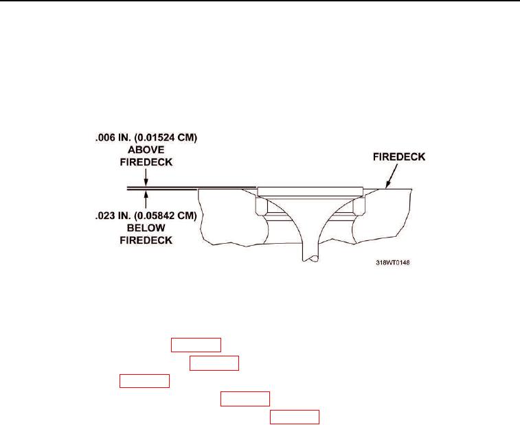
NOTE
Exhaust valves are allowed a clearance of 0.006 in. (0.01524 cm) above the fire deck to
0.023 in. (0.05842 cm) below fire deck (Figure 2).
10.
Using dial indicator, measure exhaust valve (Figure 1, Item 6) clearance to fire deck. Replace any exhaust
valves (Figure 1, Item 6) that fail.
Figure 2. Valve Clearance.
END OF TASK
1.
Install cylinder head push rods (WP 0054).
2.
Install cylinder head cam followers (WP 0053).
3.
Install fuel injectors (WP 0091).
4.
Install cylinder head exhaust valve bridge (WP 0058).
5.
Install cylinder head poppet valve rocker arm covers (WP 0049).
END OF TASK
END OF WORK PACKAGE